
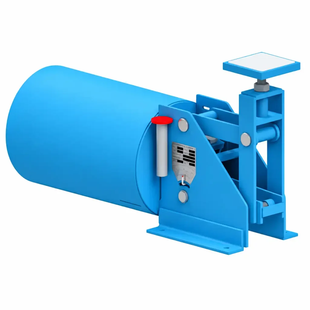
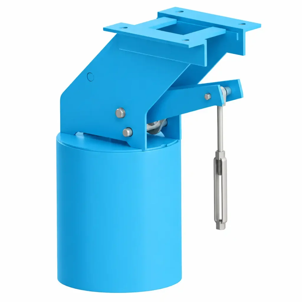
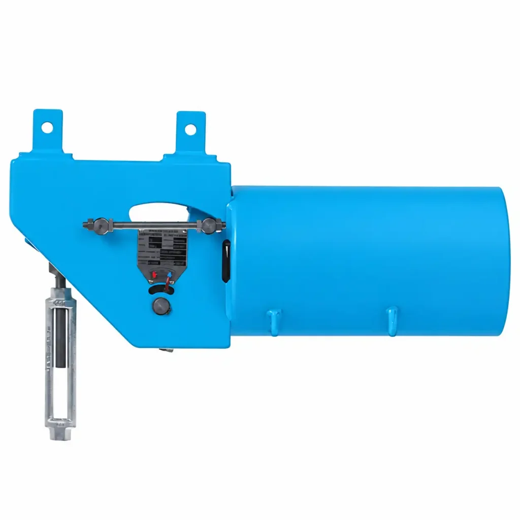
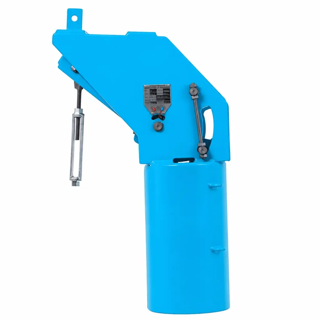
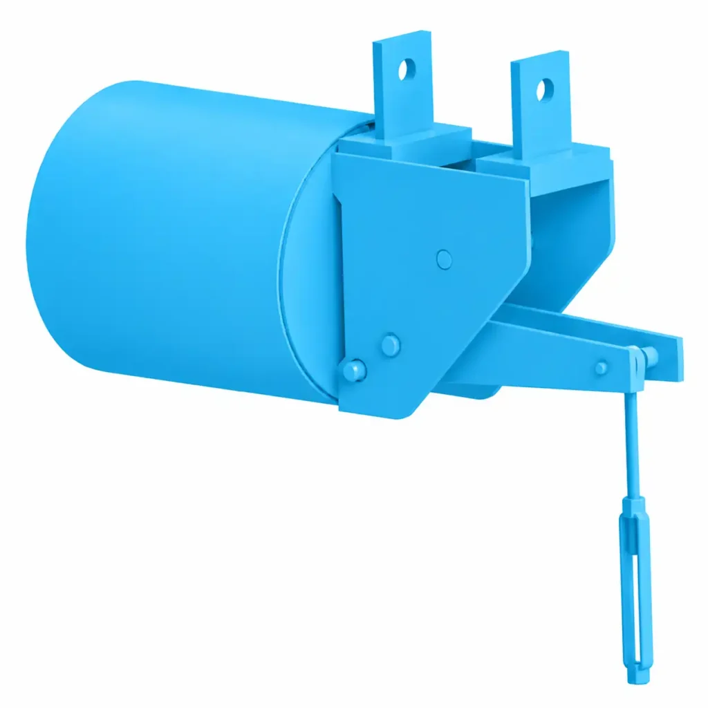
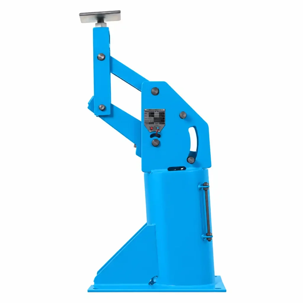
Definition, use and supplier of Constant Spring Support
A Constant Spring Support is a device comprising a spring or series of springs and an integral cam mechanism, is specifically used to accommodate constant effort load. It provides constant support forces for piping systems which move vertically due to thermal expansion or contraction. They are constructed to accommodate loads between 8 kg and 33500 kg with a standard range of travels between 40 mm and 610 mm in 10 mm increments. They are made in nine different frame sizes and 110 spring sizes to accommodate travels from 13⁄4″ to 20″ and loads from 27 lbs to 87,500 lbs.
These Constant Effort Supports are commonly installed in high-temperature steam, power plants, process industries, refineries, chemical plants, boiler systems, steam piping or other industrial applications. These supports provide nearly constant supporting force throughout the pipe’s operating movement, reducing load variation on the piping and connected equipment. They are necessary when conventional rigid or variable spring supports cannot safely accommodate large thermal displacements.
Royal Engineering Corporation is a leading Constant Spring Support supplier up to 40 tons load bearing capacity and offering reliable and high-quality piping support solutions for industrial applications. With 20 years of industry experience, we have developed a complete manufacturing setup for producing Constant Effort Spring Support according to customer requirements and project specifications. As an ISO 9001:2015 certified company, we are strongly committed to quality, precision, consistency and customer satisfaction. Our quality-minded approach ensures that every Constant Support is manufactured with careful attention to engineering requirements, material selection, fabrication, inspection and finishing. We offer competitive rates without compromising product quality, making our Spring Support a cost-effective choice for industrial piping projects. Our well-established manufacturing facilities and experienced technical team also enable us to provide faster delivery and dependable order execution. The company provides durable, accurately manufactured and dependable Pipe Supports backed by professional service and technical expertise.
Constant vs Variable Spring Support – differences between them
A Variable Spring Support changes its supporting force as the pipe moves up or down, whereas a Constant Spring maintains a consistent supporting load. Constant load Spring Supports maintain a near-uniform supporting force throughout vertical pipe movement, while variable spring supports allow controlled load variation as the spring deflects. Variable Spring hangers support piping that moves vertically, where constant supports are not required. The key differences between them are described in the table below :
| Difference | Constant Spring Support | Variable Spring Support |
|---|---|---|
| Construction |
Consists of a helical spring combined with a mechanical
compensation mechanism, generally using a lever, cam or
equivalent arrangement. The mechanism compensates for the
change in spring force as the pipe moves vertically.
MSS SP-58 Type: 54, 55, 56 Main components: spring, casing, lever/cam mechanism, load adjustment mechanism, travel indicator and limit stops. |
Consists mainly of a helical spring, spring casing and
hanger/support arrangement. Spring force changes directly
with spring deflection.
MSS SP-58 Type: 51, 52, 53 Spring models: S = Standard SS = Short Spring LS = Long Spring |
| Specification |
MSS SP-58 constant support types:
Type 54 = Constant Hanger Type 55 = Constant Hanger Type 56 = Constant Double-Rod Hanger Maximum mean load deviation: 6% Minimum field load adjustment: ±10% Travel scale: Required Load adjustment scale: Required Hot and cold settings: Required Manufacturer calibration: Required Hydrostatic test capacity with auxiliary stops: 2.0 × normal operating load |
MSS SP-58 variable support types:
Type 51 = Variable Hanger Type 52 = Variable Base Support Type 53 = Variable Double-Rod Hanger Maximum commonly specified variability: 25% Spring rate: N/mm or lbf/in Operating load: N or lbf Pipe travel: mm or in Hydrostatic test capacity with auxiliary stops: 2.0 × normal operating load |
| Load Variation |
Designed to maintain almost constant supporting force throughout
the complete operating travel.
Maximum deviation: 6% Example: Specified load = 10,000 N Approximate 6% deviation = 600 N Approximate load range = 9,400–10,600 N |
Supporting load changes according to spring deflection.
Maximum commonly specified variability: 25% Example: Operating load = 10,000 N 25% variation = 2,500 N Simplified load range = 7,500–12,500 N |
| Vertical Travel |
Used where vertical thermal movement is large and load variation
must remain within 6%.
MSS SP-58 spring-support selection reference: ≤ 6 mm ≤ 25 mm ≤ 76 mm > 76 mm Constant supports are particularly applicable when a variable spring cannot satisfy the required load-variation limit. |
Used for vertical movement where calculated variability remains
within the specified limit.
MSS SP-58 selection ranges: ≤ 6 mm ≤ 25 mm ≤ 76 mm > 76 mm |
| Calculation |
Constant support performance is evaluated from the maximum
downward reading and minimum upward reading.
Deviation: Deviation (%) = [(Max. Down Reading – Min. Up Reading) / (Max. Down Reading + Min. Up Reading)] × 200 Acceptance criterion: ≤ 6% |
Variable spring performance is calculated from pipe travel,
spring rate and operating load.
Variability factor: Variability (%) = [Pipe Travel (mm) × Spring Rate (N/mm) / Operating Load (N)] × 100 Common maximum criterion: ≤ 25% |
| Numerical Example |
Assume:
Operating load = 10,000 N Vertical travel = 100 mm Required deviation = ≤ 6% The constant mechanism must compensate for the spring-force change so that the measured supporting-load deviation remains within 6%. |
Assume:
Operating load = 10,000 N Vertical travel = 100 mm Spring rate = 20 N/mm Variability: (100 × 20 / 10,000) × 100 = 20% Result: 20% < 25%, therefore the calculated variability satisfies the commonly specified 25% criterion. |
| Application |
Used where vertical thermal movement produces significant changes
in support load and connected equipment loading must be minimized.
Typical applications: 1. Steam piping 2. Boiler piping 3. Turbine piping 4. High-temperature process piping 5. Critical equipment connections 6. Large vertical thermal movement |
Used where vertical thermal movement can be accommodated with
acceptable support-load variation.
Typical applications: 1. Process piping 2. Utility piping 3. Steam lines 4. Industrial piping 5. Moderate vertical thermal movement |
| Support Configuration |
Single-rod configuration:
Type 54, Type 55 Double-rod configuration: Type 54, Type 55, Type 56 Base support: Type 54, Type 55 |
Single-rod configuration:
Type 51 Double-rod configuration: Type 51, Type 53 Base support: Type 52 |
| Spring Rate |
The spring has a spring rate, but the mechanical compensation
arrangement offsets most of the resulting force change.
Spring rate unit: N/mm or lbf/in Final support-load deviation: ≤ 6% |
The spring rate directly controls the change in supporting load.
Spring rate unit: N/mm or lbf/in Higher spring rate + higher travel = higher load variation. |
| Thermal Movement |
Preferred where vertical movement is large and the support load
must remain nearly constant.
Design requirement: Load deviation ≤ 6% Applicable travel: 6 mm, 25 mm, 76 mm and >76 mm categories |
Suitable where thermal movement can be supported with acceptable
change in load.
Design requirement: Variability ≤ 25% Applicable travel: 6 mm, 25 mm, 76 mm and >76 mm categories |
| Costing |
Initial cost is generally higher because of the additional
compensation mechanism and greater mechanical complexity.
Cost depends on: 1. Operating load (N) 2. Required travel (mm) 3. Type 54, 55 or 56 4. Material 5. Support configuration 6. Manufacturer 7. Quantity 8. Project specification There is no universal MSS SP-58 fixed price. |
Initial cost is generally lower because the construction is
mechanically simpler.
Cost depends on: 1. Operating load (N) 2. Required travel (mm) 3. Spring rate (N/mm) 4. Type 51, 52 or 53 5. Material 6. Support configuration 7. Manufacturer 8. Quantity 9. Project specification There is no universal MSS SP-58 fixed price. |
| Maintenance |
Requires inspection of the spring, compensation mechanism,
travel indicator, load setting and limit stops.
Field load adjustment capability: ±10% minimum |
Simpler maintenance because the support does not normally contain
a mechanical constant-load compensation mechanism.
Main checks: 1. Spring condition 2. Spring rate 3. Load setting 4. Travel 5. Hanger components |
| Selection Basis |
Select using:
Operating load = N Vertical travel = mm Required deviation = ≤ 6% Support type = 54 / 55 / 56 Field adjustment = ±10% |
Select using:
Operating load = N Vertical travel = mm Spring rate = N/mm Allowable variability = ≤ 25% Support type = 51 / 52 / 53 |
Installation guide of Constant Spring Support
Installing a constant spring support correctly is essential for maintaining the intended load distribution and accommodating vertical thermal movement in piping systems. These supports are commonly used where large pipe displacement occurs and support-load variation must remain low, typically within a specified limit such as 6%. A proper installation process includes checking the approved drawings, verifying the support rating, inspecting components, securing structural attachments, connecting the pipe hanger, transferring the load gradually, and setting the correct cold position. Hydrostatic testing, removal of temporary stops, travel verification, and final inspection are also important. Following the manufacturer’s instructions and applicable standards helps ensure reliable, safe, and long-lasting performance. Follow the step-by-step installation guide below :
Review the approved support drawing : Before starting installation, carefully review the approved piping isometric, support drawing, spring hanger schedule, equipment layout and manufacturer’s data sheet. Confirm the constant spring support type, tag number, operating load, cold load, hot load, vertical travel, spring setting and installation position. MSS SP-58 identifies constant spring supports as Types 54, 55 and 56. Verify that the selected support has adequate total travel for the calculated pipe movement. The standard recommends providing travel reserve equal to the greater of 25 mm or 20% of the actual calculated travel. Confirm the support elevation, rod arrangement, attachment points and all dimensions before moving the equipment to the installation location.
Inspect the Constant Spring Support : Inspect the constant spring support before installation for transportation damage, corrosion, distorted components, damaged threads, loose hardware or missing accessories. Confirm that the nameplate information matches the approved support schedule, particularly the tag number, operating load and travel capacity. Constant supports are factory-calibrated, so the supplied unit should not be dismantled or internally adjusted at the site unless specifically authorized by the manufacturer. Check the travel indicator, load adjustment mechanism, spring casing, hanger rods, turnbuckle or load coupling and travel stops. Verify that the required hydrostatic-test stops or blocks are available when specified. Do not remove factory-installed travel stops during transportation or initial handling.
Verify the supporting structure : Confirm that the structural beam, pipe rack, concrete structure or equipment-supporting steel is capable of carrying the specified constant-support load. The attachment point must correspond to the approved support drawing, because incorrect positioning can change the hanger geometry and pipe elevation. For hanger-type constant supports, the support should be located so that the load coupling or turnbuckle is directly above the intended pipe attachment point in the operating position. Check the required center-to-center dimensions, rod lengths and available installation clearance. The supporting structure must not interfere with the movement of the loading arm or hanger rod. Structural adequacy should be verified before transferring the pipe load to the support.
Install the upper attachment and hanger rod : Install the upper attachment, beam clamp, welded attachment or structural connection according to the approved engineering drawing. Connect the constant support to the structure using the specified hanger rod, clevis, turnbuckle or threaded assembly. Ensure that threaded components have sufficient and full usable thread engagement. MSS SP-58 requires adjustment arrangements to retain full usable thread engagement and prohibits adjustments that reduce the effective engagement below the required condition. Check the vertical alignment of the hanger and make sure the rod is not bent, twisted or forced sideways. The hanger rod and loading arm must remain unobstructed so that the constant mechanism can move freely throughout its complete operating travel.
Connect the pipe attachment : Connect the lower hanger rod, pipe clamp, clevis, lug or other approved attachment to the pipe-support point shown on the drawing. Confirm that the connection is installed at the correct centerline elevation and that the pipe load is transferred through the intended structural load path. Do not introduce unintended side loads into the constant support. The hanger assembly should be aligned with the pipe attachment point in the operating position. Check that all nuts, pins, cotter pins and locking devices are correctly installed. For large or heavy piping, verify that the support is actually carrying its intended load rather than relying only on visual inspection. Temporary bracing should remain in place until the piping system is stable.
Transfer the pipe load to the support : After the connection is complete, gradually transfer the pipe load to the constant spring support using the manufacturer-specified load coupling or turnbuckle. The adjustment should normally be made in a controlled manner to eliminate slack without creating impact loading or unintended pipe displacement. For example, representative manufacturer instructions direct the installer to turn the load coupling so that the upper and lower rods are drawn together until slack is eliminated. Observe the travel indicator and confirm that the support is responding correctly. Never force a travel stop or apply uncontrolled mechanical force to the constant mechanism. The piping should remain adequately braced during installation until the complete support system is installed and stable.
Carry out hydrostatic test preparation : If a hydrostatic test is required, install the specified hydrostatic-test stops, temporary supports or auxiliary load-carrying devices before filling the piping system with test water. MSS SP-58 states that hydrostatic testing should not begin until hanger assemblies have been properly installed, adjusted and loaded according to the hanger drawings. When auxiliary hydrostatic stops are provided, the constant support is required to have a capacity of up to 2.0 times the normal operating load. For example, a support with a normal operating load of 10,000 N would require a 20,000 N capacity where the applicable hydrostatic-stop requirement applies. Follow the project hydrotest procedure and the support manufacturer’s instructions exactly.
Remove hydrostatic stops after testing : After the hydrostatic test has been successfully completed and the test water has been drained, remove or back off temporary hydrostatic stops, auxiliary supports and other temporary load-carrying devices as specified by the project procedure. MSS SP-58 requires devices furnished specifically for hydrostatic testing to be removed after completion of the test. Manufacturer instructions also caution that hydro-test blocks or stops must not remain engaged during normal operation unless specifically designed for that purpose. Travel stops must never be forced out of position. The mechanism should first be brought to the correct disengagement condition using the specified load coupling or adjustment method. Store removed components securely in their designated location for future maintenance or testing.
Set the cold position : Once testing is complete and the temporary supports are removed, adjust the constant spring support to the specified cold position shown on the approved drawing. The cold position represents the intended installation setting before the piping reaches its operating temperature. Use the manufacturer’s load-coupling or adjustment mechanism and verify the travel indicator against the supplied cold mark or cold setting. Some manufacturers use color-coded indicators, such as white for cold, red for hot and blue for maximum available travel; however, these colors are manufacturer-specific and must not be treated as universal requirements. Confirm that the indicator, load setting and pipe elevation correspond to the approved installation values before commissioning.
Verify travel and operating direction : Before commissioning, inspect the complete constant-support assembly and confirm that its travel mechanism can move freely without contact, binding or obstruction. Check the hanger rod, loading arm, turnbuckle, pipe attachment, guide clearances and surrounding steelwork. Confirm that the calculated vertical pipe movement agrees with the available travel range. MSS SP-58 recommends adequate travel reserve, with the recommended reserve being at least 25 mm or 20% of actual travel, whichever is greater. Verify that the constant mechanism is installed in the orientation for which it was calibrated. Particular attention is necessary if the manufacturer calibrated the support in a position different from its final installed orientation because installation position can affect calibration behavior.
Check the support during initial operation : When the piping system is brought gradually toward its normal operating temperature, observe the constant spring support and its travel indicator. The pipe should move smoothly in the direction predicted by the piping stress analysis without binding the hanger, loading arm or connected structure. The indicator should approach the manufacturer’s specified hot position at the normal operating condition. Do not arbitrarily force the indicator into the hot position if the actual pipe movement differs from the engineering prediction. Manufacturer installation guidance recommends contacting the piping designer when the indicator is not at or near the expected hot position. Any adjustment made during operation should be documented and reviewed because an adjustment can alter the final support load and pipe elevation.
Perform final inspection and documentation : The final inspection should verify the complete hanger assembly against the approved drawing and manufacturer documentation. Check that all components are installed, threaded connections have adequate engagement, locking nuts and cotter pins are secure, travel stops intended for normal operation are correctly positioned, and temporary supports have been removed. Record the final cold setting, hot operating position, support tag number, operating load, calculated travel and any site adjustment. MSS SP-58 specifically requires inspection of hanger assemblies before hydrostatic testing and verification of locking devices and components. For constant supports, confirm that the factory calibration information is available and retained with the project records. Proper documentation provides a baseline for future maintenance, troubleshooting, inspection and operating-condition verification.